- Joined
- Oct 22, 2014
- Messages
- 337
- Reaction score
- 147
- Joined
- Mar 10, 2015
- Messages
- 122
- Reaction score
- 50
I would go as far as to say these are the same thing. You might consider programming to be manipulating your computer, but it's also an interaction with it - you do, after all, write code with computers. When I interact, I change the internal state of my computer; when I manipulate it, I also change the internal state. Fundamentally, there isn't really a difference between the two.I'd like to see a system that can be manipulated by a player. My average system can be interacted with by players but not really manipulated, it works in the exact way I planned it. I want something where the player can change stuff.
if you accept this challenge, make it open so I can dissect it. Learn from it. I am not looking for a system I need, I am looking for knowledge and tricks. a platform with your best logic gate tricks will also do.
Please tag/quote me so I don't forget about this post :D
The real question is what would I manipulate? How would I manipulate it? The only real difference between programming with an IDE and using a magnetized needle to flip bits on your hard drive is the user interface. Similarly, in starmade, if I really want to manipulate your logic, I can just go into build mode and reconfigure it myself. If you want to present a better user interface for that (so that I don't need to know logic to change the system), all you've really done is create a bigger system with more buttons. Then you're back to square one - how do you manipulate that system?
All systems are just systems. They have inputs, an internal state, and outputs. You give the system inputs to change the internal state to what you want, then take the output. No more, no less.
It sounds like you're asking for something turing complete, which for all intents and purposes is a full computer. While certainly not impossible, it's probably beyond your size limit.
- Joined
- Jul 30, 2013
- Messages
- 398
- Reaction score
- 282
Monchoman45 i see that youtube video when autor do... the big problem is, in minecraft you can use " command block " for interact with the minecraft world, and that game have the posibility to can interact with external programs.. but as far i know, StarMade no ( if i have a mistake on this.. PLEASE TELL ME HOW )
In minecraft you can use "Mods" to do real programs ( i love computercraft and i do several LUA programs for the servers i was mod / admin ) but in StarMade, you cant do that... i mean ... i can decompres some files from SM.. edit ... and add it again to SM, but nothing more
[DOUBLEPOST=1458696289,1458696254][/DOUBLEPOST][DOUBLEPOST=1458696254,1458696128][/DOUBLEPOST]
a system to load - unload stuff from entity A to B and vice versaWhat exactly do you mean "loading and unloading stuff system"? Cargo?
- Joined
- Mar 10, 2015
- Messages
- 122
- Reaction score
- 50
There are starmade mods, but I don't know anything about them. Megacrafter probably does, though.Monchoman45 i see that youtube video when autor do... the big problem is, in minecraft you can use " command block " for interact with the minecraft world, and that game have the posibility to can interact with external programs.. but as far i know, StarMade no ( if i have a mistake on this.. PLEASE TELL ME HOW )
In minecraft you can use "Mods" to do real programs ( i love computercraft and i do several LUA programs for the servers i was mod / admin ) but in StarMade, you cant do that... i mean ... i can decompres some files from SM.. edit ... and add it again to SM, but nothing more
You don't need mods to make a turing complete computer, though - people made redstone computers in vanilla minecraft before command blocks, they were just ungodly huge. Starmade's logic system is way cleaner, so a computer in starmade would be smaller, but it would still be a massive undertaking. And probably not that useful, really - chances are you can do much better with a handful of specialized circuits.
- Joined
- Jul 30, 2013
- Messages
- 398
- Reaction score
- 282
yess Monchoman45, i love play with logic circuits, programning, mods .. the problem comes when you want build anything... but that thing dont have a specific function.. i mean.. - heyyy!! i can build a computer in starmade !! - .. and people said .. - hummm.. ok, what can we do with that? push a button and turn on a light? - i hope you get what i mean ... if people do any complicated logic system without any specific use ( destroy the ships of other players and have the most powerful ship ).
The real challenger of StarMade logic is make your best building and show to all people, but not to prove you're the best, to challenge others to better themselves and teach how things are done ... at least that's my thinking
The real challenger of StarMade logic is make your best building and show to all people, but not to prove you're the best, to challenge others to better themselves and teach how things are done ... at least that's my thinking
Last edited:
- Joined
- Feb 16, 2016
- Messages
- 67
- Reaction score
- 42
With the current state of SM logic, a computer's only purpose is lag generation :D. If there were integrated circuits (as suggested quite a lot of times) it would generate much less lag.
And in the end: it's absolutely useless, of course, but that's not the point")
And in the end: it's absolutely useless, of course, but that's not the point
- Joined
- Jan 25, 2015
- Messages
- 964
- Reaction score
- 225
integrated circuits? I will reply to you tomorrow monchoman, got to time to read and type alot atmWith the current state of SM logic, a computer's only purpose is lag generation :D. If there were integrated circuits (as suggested quite a lot of times) it would generate much less lag.
And in the end: it's absolutely useless, of course, but that's not the point
- Joined
- Oct 22, 2014
- Messages
- 337
- Reaction score
- 147
Oh, right on. I can already do that.a system to load - unload stuff from entity A to B and vice versa
- Joined
- Jan 25, 2015
- Messages
- 964
- Reaction score
- 225
GalactusX your binary system can be upgraded to using less blocks and space and connections.
here is the gif:
chain the flip flops and use a button to the beginning of the chain to go forward/backward
and use a button connected to all flipflops to go backwards/forwards.
thanks for the circuits sadly there wasn't anything new for me, probably other people will need it anyways :D
here is the gif:
chain the flip flops and use a button to the beginning of the chain to go forward/backward
and use a button connected to all flipflops to go backwards/forwards.
thanks for the circuits sadly there wasn't anything new for me, probably other people will need it anyways :D
- Joined
- Jul 30, 2013
- Messages
- 398
- Reaction score
- 282
thanks for the circuits sadly there wasn't anything new for me, probably other people will need it anyways :D
I still have not put everything I wanted, which are circuits that use as "memories" ... when I made the post was 3 in the morning, and had the exhausted body. Dont worry, i gong to update my post with more logic circuits
Last edited:
- Joined
- Mar 1, 2015
- Messages
- 291
- Reaction score
- 177
If I may ask, what is an effective solution for taking multiple inputs from a number pad and then converting it into a single binary number? I have attempted this using a table of x(10^y). X being the number on the numpad, and Y being the place. It is hardly compact, and it relies on an adder to work. Any better solution?
Also, for memory, I have found a way to allow you to delete and write over a memory cell in one operation. It involves instant pulses. If you want, I could explain how it works.
EDIT:
In time, I will be able to prove you wrong. In time.
Also, for memory, I have found a way to allow you to delete and write over a memory cell in one operation. It involves instant pulses. If you want, I could explain how it works.
EDIT:
Regarding the usefulness of ingame computers:With the current state of SM logic, a computer's only purpose is lag generation :D. If there were integrated circuits (as suggested quite a lot of times) it would generate much less lag.
And in the end: it's absolutely useless, of course, but that's not the point
In time, I will be able to prove you wrong. In time.
Last edited:
- Joined
- Feb 16, 2016
- Messages
- 67
- Reaction score
- 42
1.If I may ask, what is an effective solution for taking multiple inputs from a number pad and then converting it into a single binary number? I have attempted this using a table of x(10^y). X being the number on the numpad, and Y being the place. It is hardly compact, and it relies on an adder to work. Any better solution?
Also, for memory, I have found a way to allow you to delete and write over a memory cell in one operation. It involves instant pulses. If you want, I could explain how it works.
...
Regarding the usefulness of ingame computers:
In time, I will be able to prove you wrong. In time.
I guess you want an input like of a calculator: the user presses a digit, the number shifts to the left one position (i.e. gets multiplied by 10) and the newly pressed digit is added. After each button press, the number stored must first be multiplied by 10 (or 1010 binary) and the button's value must be added (it's in the range 0000-1001) .
Binary multiplication by 10 is left shift by 3 plus left shift by 1. Then another addition for a total of 2 additions and 2 shifts on each step:
Vn+1 = 10Vn + Dn+1 = 8Vn + 2Vn + Dn+1 = Vn<<3 + Vn<<1 + Dn+1
where Dn is the n-th digit pressed and Vn is the value after this. V0 is zero. I have to test this, but analytically solving it seems more compact and easier than using a table (no integrated circuits, remember
). No way to skip adders here too.And since we don't know your solution, we cannot know if a better one is possible
.2.
Personally, I'd be very happy to see your memory cell! I guess it uses a flip-flop ?
3.
Regarding computers -- a general purpose computer is a gargantuan project. I started building mine, the bus itself only was a huge thing. After the register and the ALU, when I was building the instruction fetch I decided to put it on hold. An XOR gate would have helped me a lot. And the 1 Hz speed limit.... A more specific computer (like a game console or something) would be both easier and more useful, imho.
Last edited:
- Joined
- Jul 30, 2013
- Messages
- 398
- Reaction score
- 282
I update the post with 2 memory logic circuits, i move the LOGIC CIRCUITS to the first post page
Last edited:
- Joined
- Mar 1, 2015
- Messages
- 291
- Reaction score
- 177
1: Cool, but it seems to cost a lot of operations. When I said table, I was referring to using a grid of ANDs to represent values. Each number had three possible values, for example, 1 would have these values: 100,10, and 1. The result is a little large, but runs in one operation.1.
I guess you want an input like of a calculator: the user presses a digit, the number shifts to the left one position (i.e. gets multiplied by 10) and the newly pressed digit is added. After each button press, the number stored must first be multiplied by 10 (or 1010 binary) and the button's value must be added (it's in the range 0000-1001) .
Binary multiplication by 10 is left shift by 3 plus left shift by 1. Then another addition for a total of 2 additions and 2 shifts on each step:
Vn+1 = 10Vn + Dn+1 = 8Vn + 2Vn + Dn+1 = Vn<<3 + Vn<<1 + Dn+1
where Dn is the n-th digit pressed and Vn is the value after this. V0 is zero. I have to test this, but analytically solving it seems more compact and easier than using a table (no integrated circuits, remember
And since we don't know your solution, we cannot know if a better one is possible
2.
Personally, I'd be very happy to see your memory cell! I guess it uses a flip-flop ?
3.
Regarding computers -- a general purpose computer is a gargantuan project. I started building mine, the bus itself only was a huge thing. After the register and the ALU, when I was building the instruction fetch I decided to put it on hold. An XOR gate would have helped me a lot. And the 1 Hz speed limit.... A more specific computer (like a game console or something) would be both easier and more useful, imho.
I was building a calculator, but it turned out to be such a mess that I couldn't finish it. Something was wrong with how I plugged in the adder, and the CU was such a confused mess of circuitry that I couldn't fix it. Nevertheless, I am confident that a second pass will succeed. Especially thanks to your explanation.
2: Yes, and based on your question, I am pretty sure you know exactly how its built. I wonder, I have found that instant pulses behave strangely. Have you noticed that when you use flip-flops and ANDs to generate instant pulses, you sometimes have to put an extra button? Otherwise it stays on, and is unusable for resetting circuits. It might have to do with the grid system.
3: I have the beginnings of a baby computer started. A complete, yet somewhat wonky ALU. No NOT operation, but a NAND. You have to use NOR with zero as the other number to get NOT. No CU or memory yet, but I can definitely perform operations using only the bus and the opcode selector. Once I complete it, I am going to try to condense it down a bit before I use it for its ultimate purpose!
- Joined
- Feb 16, 2016
- Messages
- 67
- Reaction score
- 42
Trekkerjoe ,
I was planning to build a simple calculator, but I still need to figure how to represent numbers: either binary or dec-hex (each digit is an independent 4bit cell with 6 'forbidden' states). Binary is better for calculations, dec-hex is better for display & input.
FFs not only react to instant pulses but they actually count them. That's why a 'bounce-back' AND gate is required to revert the FF to 0. The FF is able to distinguish it's input from the bounce-back, though both signals might appear simultaneous. Due to this instant pulse sensitivity, for memory cells I prefer RS latches, which have 'inertia'.
EDIT: It seems that and gates are not sensitive to instant pulses in the expected way. An up edge may not activate it, while a down edge may not deactivate it and 'stall' it in erroneous state. I'm still trying how to figure out these irregularities and use them in a predictable way. My goal is to acquire 'micro delays'. These sometimes work, others -- not.
Attached you'll find a possible solution to your problem. It is compact, simple and easily extendable to any bit length, but it's slow because it uses my favourite FF Chains and requires 3 delays.
It contains 3 FF chains. The value V is displayed on the top one. The bottom one (accumulator) holds -10V. This is where the numpad inputs. The middle contains 9V and does the shifting. The numpad's layout is like of a computer's : 0 bottom, 1 -- bottom-left, ... 5 - middle, ... 9- top-right. There is a RS latch after the numpad as spam prevention. When it's 'up', the circuit is ready to accept the next number.
(On the right there is a small instant pulse chain which shows the differences between FFs and RS nors).

I was planning to build a simple calculator, but I still need to figure how to represent numbers: either binary or dec-hex (each digit is an independent 4bit cell with 6 'forbidden' states). Binary is better for calculations, dec-hex is better for display & input.
FFs not only react to instant pulses but they actually count them. That's why a 'bounce-back' AND gate is required to revert the FF to 0. The FF is able to distinguish it's input from the bounce-back, though both signals might appear simultaneous. Due to this instant pulse sensitivity, for memory cells I prefer RS latches, which have 'inertia'.
EDIT: It seems that and gates are not sensitive to instant pulses in the expected way. An up edge may not activate it, while a down edge may not deactivate it and 'stall' it in erroneous state. I'm still trying how to figure out these irregularities and use them in a predictable way. My goal is to acquire 'micro delays'. These sometimes work, others -- not
.Attached you'll find a possible solution to your problem. It is compact, simple and easily extendable to any bit length, but it's slow because it uses my favourite FF Chains and requires 3 delays.
It contains 3 FF chains. The value V is displayed on the top one. The bottom one (accumulator) holds -10V. This is where the numpad inputs. The middle contains 9V and does the shifting. The numpad's layout is like of a computer's : 0 bottom, 1 -- bottom-left, ... 5 - middle, ... 9- top-right. There is a RS latch after the numpad as spam prevention. When it's 'up', the circuit is ready to accept the next number.
(On the right there is a small instant pulse chain which shows the differences between FFs and RS nors).
Attachments
-
3.7 KB Views: 32
Last edited:
- Joined
- Jul 30, 2013
- Messages
- 398
- Reaction score
- 282
The last 2 days to make your vote in the poll logical challenge !! Make your choice
[DOUBLEPOST=1459009177,1459006188][/DOUBLEPOST]
[DOUBLEPOST=1459009177,1459006188][/DOUBLEPOST]
1: Cool, but it seems to cost a lot of operations. When I said table, I was referring to using a grid of ANDs to represent values. Each number had three possible values, for example, 1 would have these values: 100,10, and 1. The result is a little large, but runs in one operation.
I was building a calculator, but it turned out to be such a mess that I couldn't finish it. Something was wrong with how I plugged in the adder, and the CU was such a confused mess of circuitry that I couldn't fix it. Nevertheless, I am confident that a second pass will succeed. Especially thanks to your explanation.
2: Yes, and based on your question, I am pretty sure you know exactly how its built. I wonder, I have found that instant pulses behave strangely. Have you noticed that when you use flip-flops and ANDs to generate instant pulses, you sometimes have to put an extra button? Otherwise it stays on, and is unusable for resetting circuits. It might have to do with the grid system.
3: I have the beginnings of a baby computer started. A complete, yet somewhat wonky ALU. No NOT operation, but a NAND. You have to use NOR with zero as the other number to get NOT. No CU or memory yet, but I can definitely perform operations using only the bus and the opcode selector. Once I complete it, I am going to try to condense it down a bit before I use it for its ultimate purpose!
you mean this equal table convert?Trekkerjoe ,
I was planning to build a simple calculator, but I still need to figure how to represent numbers: either binary or dec-hex (each digit is an independent 4bit cell with 6 'forbidden' states). Binary is better for calculations, dec-hex is better for display & input.
FFs not only react to instant pulses but they actually count them. That's why a 'bounce-back' AND gate is required to revert the FF to 0. The FF is able to distinguish it's input from the bounce-back, though both signals might appear simultaneous. Due to this instant pulse sensitivity, for memory cells I prefer RS latches, which have 'inertia'.
EDIT: It seems that and gates are not sensitive to instant pulses in the expected way. An up edge may not activate it, while a down edge may not deactivate it and 'stall' it in erroneous state. I'm still trying how to figure out these irregularities and use them in a predictable way. My goal is to acquire 'micro delays'. These sometimes work, others -- not
Attached you'll find a possible solution to your problem. It is compact, simple and easily extendable to any bit length, but it's slow because it uses my favourite FF Chains and requires 3 delays.
It contains 3 FF chains. The value V is displayed on the top one. The bottom one (accumulator) holds -10V. This is where the numpad inputs. The middle contains 9V and does the shifting. The numpad's layout is like of a computer's : 0 bottom, 1 -- bottom-left, ... 5 - middle, ... 9- top-right. There is a RS latch after the numpad as spam prevention. When it's 'up', the circuit is ready to accept the next number.
(On the right there is a small instant pulse chain which shows the differences between FFs and RS nors).
- Joined
- Jul 30, 2013
- Messages
- 398
- Reaction score
- 282

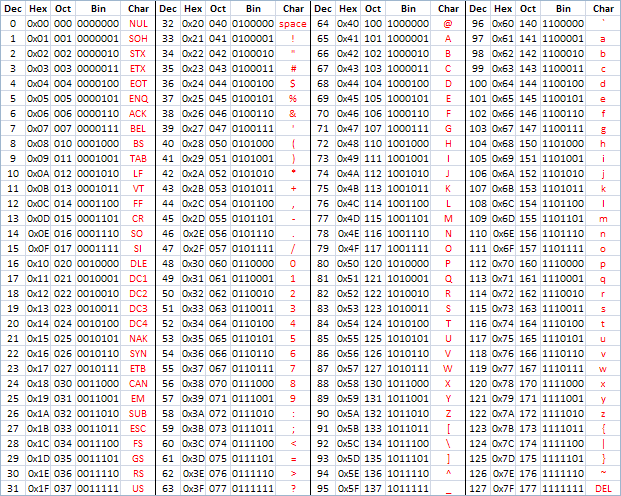
Hi all again people; all logical system or circuit, there are always three distinct parts, entries, system operations and outputs, but to see what is happening within any of these parts, we need a way to represent the data that we are working, for that, today I bring you: the controller display BINARY to BCD.
As we all know, the displays are present in the vast majority of peripheral of our daily lives, whether to tell time coción the microwave, the refrigerator temperature, time of reproduction of our favorite music ... all these devices have in common, the possibility of giving information of its internal operations.
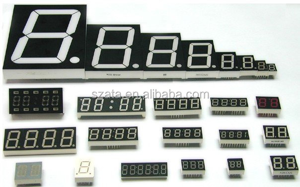
Standard 7-segments displays in diferents sizes
The most efficient way to represent a logical data is using binary code, and we need the help of a converter binary to BCD (acronym of Binary Coded in Decimal). For that, we'll need a circuit as simple as possible, which can translate the binary code to decimal to be used to benefit our needs.


This is the Display-Counter in action


If you want to have only the display and the converter to BCD, you only have to remove the flip-flops and AND gates next to the buttons.
If anyone need have a diferent Display desing, just tell me what you need, and i build it for you
Attachments
-
7.6 KB Views: 29
Last edited: