Logic Cortex -Programmable Microprocessor (WIP)

    Joined
    Mar 1, 2015
    Messages
    291
    Reaction score
    176
    • Wired for Logic
    • Community Content - Bronze 2
    • Purchased!
    I created a test platform for a 2Hz 5-Bit T-Flip-Flop PC. It is much smaller than an Adder>Register combo, yet it can jump instantly. I pulled this off by implementing a reverse counter. It seems that !(--i) is the same as ++i, so I have two reverse t-flip-flop counters going into NOTs. One is engaged with the circuit, the other is always initialized at 11111. That way I don't need any slow, buggy logic to update it, I can just create a mirror image of the data and mirror it back to whatever cache I have set up. It does take time to reinitialize the counters, but it only takes up to 1.5 seconds to update (about 3 operations) , and the delay is masked by switching between the two flip-flops.

    If you are interested in the circuit, I can put the test platform up on the CC.
     
    Joined
    Nov 3, 2013
    Messages
    19
    Reaction score
    6
    • Legacy Citizen 2
    • Community Content - Bronze 1
    Sounds like I might want to use buffered version of a t-flip flop chain instead of an adder. The problem with that system is the fact that the T-flip-flops are unstable, and you can't easily write to them. The system I had would pause the timer, erase itself and disconnect the chain, have the new address written, reconnect the chain, a filtering signal that returns the flip-flops to the imprinted signal, and update the instant memory with the new signal. There are far too many steps, and it takes over three seconds when it's over. Quite a steep penalty for something with a throughput of one operation a second.

    *Goes into brainstorm mode.*

    I might be able to update them faster if I activate all of them with a controlled pulse, send the value I want to get an inverted signal, and toggle them again to invert it back to the correct signal. It may take three clock cycles or more. Too slow for the pipeline I have planned for the next computer (which should perform operations at 2Hz) so I will have two or three of them, one that is engaged with the cache, and the other(s) will already be in the inverted state. That way the delay is masked, allowing me to run it all at 2Hz.

    EDIT: Perhaps with extra logic, I could have NOTs coming out of the T-flip-flops to temporarily invert the signal back, and allow me to update over multiple cycles without corrupting the data in the cache.

    You were also wondering about my instant memory. My setup is fairly simple. I have an AND><OR register. There is an instant pulse generator going into a NOT, going into the ANDS. Sending a signal to the instant pulse generator and the overwriting signal to the register will update it instantly, in one clock cycle. Quite useful for RAM and cache memory. The alternative is to give the circuit logic the logic to change states only if the signal being received is different, but that is a whole other circuit.
    I created a test platform for a 2Hz 5-Bit T-Flip-Flop PC. It is much smaller than an Adder>Register combo, yet it can jump instantly. I pulled this off by implementing a reverse counter. It seems that !(--i) is the same as ++i, so I have two reverse t-flip-flop counters going into NOTs. One is engaged with the circuit, the other is always initialized at 11111. That way I don't need any slow, buggy logic to update it, I can just create a mirror image of the data and mirror it back to whatever cache I have set up. It does take time to reinitialize the counters, but it only takes up to 1.5 seconds to update (about 3 operations) , and the delay is masked by switching between the two flip-flops.

    If you are interested in the circuit, I can put the test platform up on the CC.
    Iv'e tried a flip flop counter design before and the problem i had is that the flip flop chain ( if your using the flip flop blocks ) create instant pulses before the data is stable, leading to errors when you try to use that signal. It corrupts a lot of stuff unless you filter it out with a latch or a delay block. Ill take a look at the design tomorrow when i get some time, only have a 4 hour shift mostly in the morning.
     
    • Like
    Reactions: Trekkerjoe

    Fellow Starmadian

    Oh cool so thats what this is
    Joined
    Jun 7, 2014
    Messages
    227
    Reaction score
    87
    • Community Content - Bronze 1
    • Wired for Logic
    • Legacy Citizen 2
    thanks trekker, I'll have to find the time to disassemble this! love instant pulses, but unfortunately it doesn't scale too well. All the logic calculations still need to be processed,which seems to be the bottleneck atm.

    EDIT: too many commas!
     
    Joined
    Mar 1, 2015
    Messages
    291
    Reaction score
    176
    • Wired for Logic
    • Community Content - Bronze 2
    • Purchased!
    The Cortex is complete! Here is the link: Logic Cortex

    The OP was changed to be a list format. Unimpressive now, but I hope to fill it up with many different versions of the cortex in the future.
     
    Joined
    Mar 1, 2015
    Messages
    291
    Reaction score
    176
    • Wired for Logic
    • Community Content - Bronze 2
    • Purchased!
    Tested it out on a server. It broke under it's own lag. Looks like it is time to start work on the model B version. I will keep you posted.
     
    Joined
    Mar 1, 2015
    Messages
    291
    Reaction score
    176
    • Wired for Logic
    • Community Content - Bronze 2
    • Purchased!
    Yeah. It was actually quite smooth on my end. The GOTO function didn't work though, so I suspected there was lag. Problem is that I need a computer that works on servers, and my first model is very poorly optimized for it. Next time I see you on the server I'll let you take a look at it.
     
    • Like
    Reactions: terra mining corp.
    Joined
    Mar 1, 2015
    Messages
    291
    Reaction score
    176
    • Wired for Logic
    • Community Content - Bronze 2
    • Purchased!
    Update: I have remade the ALU components for the new computer:

    I decided I was going to use a 5-bit oppcode system this time, so I have double the operations to work with. In addition to this, I have no internal oppcodes anymore, instead, I am going to use a multiplexer going directly into the mode pins of the components.

    I have also decided to change how individual components are managed. I plan to only send signals through components I want a signal from, unlike the A version. With the A version, it performs many operations at once and chooses the correct output. So if you wanted to perform addition, it also performs a logical comparison and a logical operation. You can imagine this causes extra lag. Lag I hope to avoid by shutting components down when they are not in use.

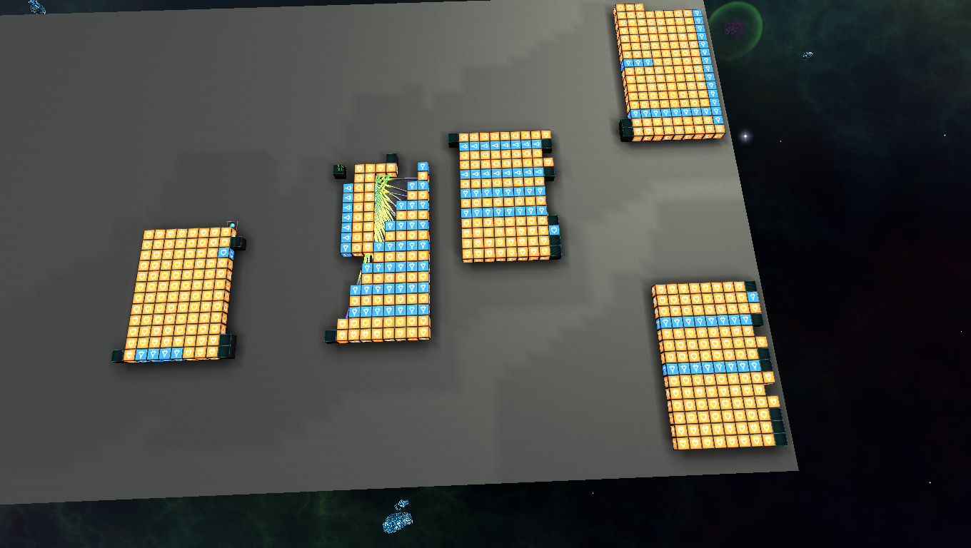
    In the top right is an improved version of the ripple-carry adder I used in the model A version. It is functionally the same as the old one, just smaller.

    Below that is a logic processor I have scratch-built for this computer. It supports AND, OR, and XOR. In addition to this, it can invert the results to get NAND, NOR, and XNOR.

    To the left of this is my comparison circuit. It takes two inputs and returns whether A and B are equal, A is greater than B, or A is less than B.

    To the left of this is an extra comparison circuit. I am not sure what to call it. It is basically a mechanism for fuzzy logic. It takes one input, and then returns the number of bits, as in how many bits are true, versus the number encoded in them. This means you can use this with XOR to get the number of different bits, or XNOR to get the number of same bits. This makes it far easier to write programs than can say "Close enough!" in a scenario like object recognition. But it has no name yet, so I have not made it a template just yet. Any suggestions?

    Finally, to the left of this is my binary-shifter. It can shift a number left or right seven places. I plan to use an error checker to check for overflow. If you shift more than seven times, the answer is always going to be 0 no matter what you are shifting.

    If there is something I'm missing, or any tips you can give me, please let me know.
     
    • Like
    Reactions: Jaaskinal
    Joined
    Mar 1, 2015
    Messages
    291
    Reaction score
    176
    • Wired for Logic
    • Community Content - Bronze 2
    • Purchased!
    Update. I have made no progress in game! Out of game, I have managed to scrape together the new specifications which I'll show you.

    Here is what I hope to be able to accomplish:
    Logic Cortex B: Oppcodes and hardware summary.

    *Hardware*

    -At least 4hz clock divided into Input/Execute>Output steps.

    -Pipeline effectively running at 2hz at least.

    -Built in hazard avoidance.

    -Interrupts.

    -A far better trainer with a text output and a dot operator assembly interface.

    -Counters, timers with interrupt support, access to program counter.

    -ALU with support for Add, Subtract, AND, OR, XOR, NAND, NOR, XNOR, Bitsum operations involving all logic, Logical comparisons, and bit shifting.

    -T-flip flop PC with instant jump capability. (Might need a second one just in case.)

    -128 registers of 17-bit program memory. 5-bit oppcode, two 4-bit register read addresses, one 4-bit register write address. 2176 bytes total.

    -16 8-bit registers.

    -At least eight ports of 16 pins(8 in, 8 out) totaling 64 in, 64 out, for 128 total.

    -Ability to use a mask to set individual pins on or off. Uses a buffer so that you can refresh all at once.

    -Four interrupt pins.

    -Modular memory cells.

    -Modular registers.

    *Oppcodes*

    -Five bit oppcode; up to 32 instructions.

    0 00000 noOperation //Does nothing but put a gap in the pipeline. Used internaly, or on purpose.

    1 00001 Constant //Stores an 8-bit constant in a register.

    2 00010 Math.Add //Adds the value of two registers, and stores the result.

    3 00011 Math.Subtract //Subtracts the value of two registers, and stores the result.

    4 00100 Logic.AND //ANDs the value of two registers, and stores the result.

    5 00101 Logic.OR //ORs the value of two registers, and stores the result.

    6 00110 Logic.XOR //XORs the value of two registers, and stores the result.

    7 00111 Logic.NAND ///NANDs the value of two registers, and stores the result.

    8 01000 Logic.NOR //NORs the value of two registers, and stores the result.

    9 01001 Logic.XNOR //XNORs the value of two registers, and stores the result.

    10 01010 Bitsum.AND //Sums the number of on bits of two variables ANDed together.

    11 01011 Bitsum.OR //Sums the number of on bits of two variables ORed together.

    12 01100 Bitsum.XOR //Sums the number of on bits of two variables XORed together.

    13 01101 Bitsum.NAND //Sums the number of on bits of two variables NANDed together.

    14 01110 Bitsum.NOR //Sums the number of on bits of two variables NORed together.

    15 01111 Bitsum.XNOR //Sums the number of on bits of two variables XNORed together.

    16 10000 If.A>B //Runs the subsequent line of code if this is true.

    17 10001 If.A<B //Runs the subsequent line of code if this is true.

    18 10010 If.A==B //Runs the subsequent line of code if this is true.

    19 10011 If.A>=B //Runs the subsequent line of code if this is true.

    20 10100 If.A<=B //Runs the subsequent line of code if this is true.

    21 10101 IF.A!=B //Runs the subsequent line of code if this is true.

    22 10110 IO.SelectPort //Selects a set of IO pins or extra hardware. 0-7 are I/O pins, 8-10 are timers.

    23 10111 IO.Write //Writes a constant value to the pins, or a register value if there is an identifying bit in the writevalue.

    24 11000 IO.ReadPins //Stores the contents of the selected input pins to a register. Each on state stored in the constant concurs with each individual pin. Uses a register value if there is an identifying bit in the writevalue.

    25 11001 IO.PinsOn //The concurring pins are set to on in the buffer. Uses a constant unless there is an identifying bit in the writevalue, in which case it uses a register. A second identifying bit skips the buffer.

    26 11010 IO.PinsOff //The concurring pins are set to off in the buffer. Uses a constant unless there is an identifying bit in the writevalue, in which case it uses a register. A second identifying bit skips the buffer.

    27 11011 IO.UpdatePins //Updates the pins with the value of the buffer so you can update all at once.

    28 11100 IO.ConfigureInterrupt //Enables and disables interrupts with an identifying bit in the writevalue. Uses other identifying bits to control timers directly. Note you can set up interrupts manually as well.

    29 11101 End // Ends an interrupt and jumps back to the previous location, otherwise stops the program until next interrupt. Jumping from an interrupt to an End negates the End.

    30 11110 Jump.Register //Jumps to an address stored in a register. Stores the previous location in a register.

    31 11111 Jump.Constant //Jumps to the address stored in program memory. Stores the previous location in a register.
    As you can probably tell, I have a lot of work ahead of me.
     
    Joined
    Jul 30, 2013
    Messages
    398
    Reaction score
    282
    • Wired for Logic Gold
    • Legacy Citizen 8
    • Purchased!

    AWESOME mate ... maybe... if we merge us into one body (like dragon ball manga ) We could dominate the universe building automatas !!!​
     
    Joined
    Mar 1, 2015
    Messages
    291
    Reaction score
    176
    • Wired for Logic
    • Community Content - Bronze 2
    • Purchased!

    AWESOME mate ... maybe... if we merge us into one body (like dragon ball manga ) We could dominate the universe building automatas !!!​
    We would be unstoppable!

    I might need your help. Just before going to bed I realized that I made a mistake. I filled up all of my oppcodes without realizing that I never made a command for binary shifting.

    It is not as bad as it sounds. There is one unused bit in the Jump command that I can use as a flag to change behavior, but still, I could have gone off and started building it before I realized what I was missing!

    Here are the updated oppcodes:

    30 11110 Shift //Performs a binary shift of the stored number. Identifying bits determine the magnitude and direction of the shift.

    31 11111 Jump //Jumps to the address stored in program memory. Stores the previous location in a register. Jumps to an address stored in a register if there is an identifying bit.
     

    DrTarDIS

    Eldrich Timelord
    Joined
    Jan 16, 2014
    Messages
    1,114
    Reaction score
    310
    Just gonna go out on a limb here and recommend you switch to a rotator as your clock so you can tweak the operation speed in an analog manner. It'll let you find out what kind of operation speed is viable on a server-server basis. Also, try running mk 1 on shine's server, you might have discovered a unique method of trumping the logic system and that's the best way to be a "good alpha tester" and get their attention. :)
     
    Joined
    Mar 1, 2015
    Messages
    291
    Reaction score
    176
    • Wired for Logic
    • Community Content - Bronze 2
    • Purchased!
    Just gonna go out on a limb here and recommend you switch to a rotator as your clock so you can tweak the operation speed in an analog manner. It'll let you find out what kind of operation speed is viable on a server-server basis. Also, try running mk 1 on shine's server, you might have discovered a unique method of trumping the logic system and that's the best way to be a "good alpha tester" and get their attention. :)
    Yes! Thanks for pointing that out. I already use the rotator clock, but it always seems to slip my mind that I can adjust the speed. Thanks to you, the B version should work much better on servers.

    Unfortunately the A version cannot be underclocked for the same reason it cannot run on servers. Too many race conditions in the logic. Probably a design flaw, not a problem with logic, but I will go in the schine server to see if I can spawn it in.
     
    Joined
    Mar 1, 2015
    Messages
    291
    Reaction score
    176
    • Wired for Logic
    • Community Content - Bronze 2
    • Purchased!
    Quick update: I had made the 3-channel register that I will have docked on the new Cortex:

    It has eight 8-bit registers, with two independent outputs, and one independent input. It is larger than my other memory cell designs, but this is because it does not use instant pulses, instead it uses conditional memory that only updates the bits that have to change. Hopefully this reduces lag on servers by removing much of the noise instant pulses cause. My plan is to have two of them plugged into the pipeline, giving the system 16 bytes of register storage.

    I also decided to make an unlocked version of the T-flip-flop program counter. The idea is that instead of two timing signals, I would feed it four signals. Two off of the main clock, and the other two with an overclocker (Which is awesome, btw alterintel ) to drastically reduce the cooldown time. It works so well that it is ready to jump again by the next cycle:

    As for performance, I can say that it is many, many times better than the one I used in the original. But, I am still debating the possible drawbacks of using this overclocked circuit on servers. It shouldn't be a problem though, as I was able to overclock a similar circuit on NFD with no problems whatsoever.
     
    Joined
    Mar 1, 2015
    Messages
    291
    Reaction score
    176
    • Wired for Logic
    • Community Content - Bronze 2
    • Purchased!
    I have finally finished the program memory of the new computer:

    There are eight memory modules on board to store 128 17-bit blocks of memory. These are docked to a holder that can undock from the computer so that you can connect cartridges with different programs. The only real drawbacks are that it relies heavily on wireless, and I think it will be larger than all the other components combined.

    If something does go wrong with the wireless, the memory cells can pop out a few blocks so that you can look at the connections.
     

    TheGT

    Chief Janitorial, Second Legion, Fourth Squadron
    Joined
    Dec 10, 2015
    Messages
    60
    Reaction score
    25
    I have finally finished the program memory of the new computer:

    There are eight memory modules on board to store 128 17-bit blocks of memory. These are docked to a holder that can undock from the computer so that you can connect cartridges with different programs. The only real drawbacks are that it relies heavily on wireless, and I think it will be larger than all the other components combined.

    If something does go wrong with the wireless, the memory cells can pop out a few blocks so that you can look at the connections.
    I would suggest the combination of plex doors and area triggers to transfer logic signals between touching entities, It will save you quite a bit of hassle with the wireless.
     

    nightrune

    Wizard/Developer/Project Manager
    Joined
    May 11, 2015
    Messages
    1,324
    Reaction score
    577
    • Schine
    • Top Forum Contributor
    • Thinking Positive
    I would suggest the combination of plex doors and area triggers to transfer logic signals between touching entities, It will save you quite a bit of hassle with the wireless.
    This works!?
     
    Joined
    Mar 1, 2015
    Messages
    291
    Reaction score
    176
    • Wired for Logic
    • Community Content - Bronze 2
    • Purchased!
    As far as I know, this doesn't work. I will test it just to make sure though.
     
    Joined
    Nov 3, 2013
    Messages
    19
    Reaction score
    6
    • Legacy Citizen 2
    • Community Content - Bronze 1
    As far as I know, this doesn't work. I will test it just to make sure though.
    I've tried this and i know it doesn't work. If you want truly plug and play data transfer (without the use of wireless logic), then you have to use rail collisions as a method of data transfer. This method of transfer is extremely slow however, the best i could get was 1 bit transferred every 4 seconds, but that was a while ago and i haven't sat down and gave it a redesign yet. Of course, the modules are fairly small and you can get more io by simply placing more of them down. Speaking of it, i think i might have lost the space optimized version of that circuit.

    Edit: Found the rail binary transfer thingy i was talking about above, and yes it is very slow, but i'm going to work on getting it faster by increasing rail speed or just multiplexing it somehow...

    To be honest, just use wireless blocks unless your using some sort of docked cargo container system and you want to know how much is in the container.
     
    Last edited: