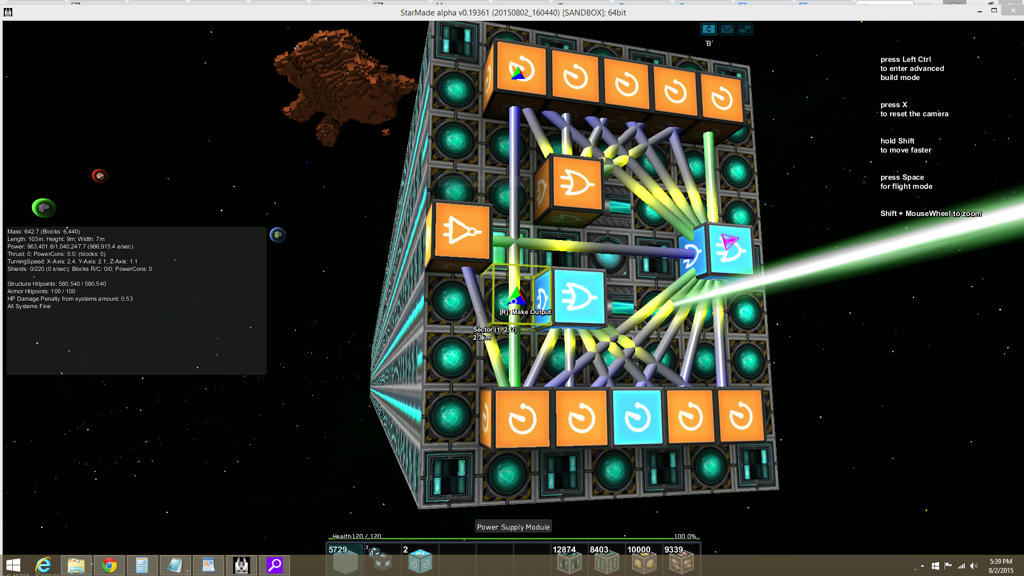
My brain is not agile enough any more to handle many of the complexities of logic circuits. This is the hack job I did to control a docked power module. It is built this way mostly to be easy for me to follow the logic of. While any of the bottom delays are active, they will activate the lower 'or' block that activates the bottom power supply beam computer. While any of the top delays are active, they will activate the upper 'or' block that activates the top power supply beam computer. All the delays feed into another 'or' block which in theory always stays 'on/high'. If for some reason however due to a reboot or whatever, the circuit is not working, that 'or' block will be off, which will activate the 'not' block to the left, which will restart the clock.
I am pretty sure this is not the ideal setup, but this is as good as my limited understanding of logic circuits can do at the moment. Sven the Slayer has
a video tutorial on clocks in which he describes what would clearly be a better clock, but despite watching it several times, I cannot understand what he has built or how it functions (my brain is not what it used to be).
Anyone care to tell me what I should do differently? I realize I could likely do away with one of the rows of delay blocks and simply invert the signal for the other beam, but the one presented is both easier to understand for my brain and visually more pretty.


